Basic Welding Positions Explained
We often hear about 1G/F, 2G/F welding positions, but what do these terms mean? What are their orientations and angles, and how are they performed? In this blog, we’ll break them down with clear explanations and illustrations to help you understand them better.
According to ISO 15614-1, ASME IX, and AWS D1.1 (official documentation), welding positions are classified based on AWS A3.0 into four main orientations: Flat, Horizontal, Vertical, and Overhead. This system helps welders, engineers, and inspectors quickly identify how a weld should be performed.
The numbers define the welding position:
1: Flat Position
2: Horizontal Position
3: Vertical Position
4: Overhead Position
The letters specify the type of weld:
G: Groove Weld
F: Fillet Weld
In welding classification, G (Groove Weld) refers to butt joints where two metal pieces join edge-to-edge, requiring deep penetration for strength. F (Fillet Weld) is used in corner, lap, or T-joints, where metal pieces meet at an angle without edge preparation.
Welding Positions: The Four Key Types
1. Flat Position:
The flat position is the most common and straightforward welding position, where the weld is performed horizontally on a flat surface. Its main advantage is stability, as gravity has minimal effect on the molten weld puddle. This makes it easier for welders to maintain control using a simple push or pull technique without needing to compensate for metal flow.
Due to this stability, the flat position is compatible with various welding processes, including MIG, TIG, and stick welding, and supports multiple metal transfer modes, such as short-circuit, globular, and spray transfer. Its ease of execution and adaptability make it widely used in automotive, construction, and shipbuilding industries, where efficiency and consistency are key.
Application Example: In the construction industry, the flat position is commonly used to weld steel plates together in the fabrication of bridges and building structures. The ability to work with large and flat surfaces makes it an efficient choice for these applications.
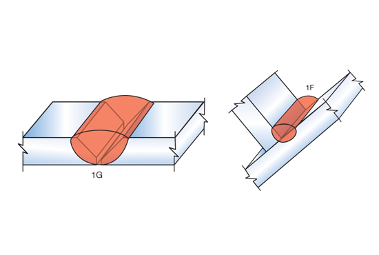
1G/1F Welding Positions
2. Horizontal Position:
If you rotate the 2G/2F diagram 90° to the left, you’ll notice that it aligns with 1G/1F, showing that the weld orientation becomes the same.
In the horizontal position, 2G is more difficult than 2F because the workpiece is fixed vertically, requiring the weld to be performed horizontally (left to right). Gravity pulls the molten weld pool downward, increasing the risk of sagging, lack of fusion, or undercut defects. Unlike 2F, where the fillet weld allows the molten metal to settle naturally in the joint, 2G groove welding requires securing the workpiece in place using tack welds to prevent misalignment. Additionally, welders must carefully control heat input, travel speed, and electrode angle to maintain proper fusion and prevent excessive fluidity. Mastering these techniques is essential for achieving a strong and defect-free 2G weld.
Application Example: In pipeline construction, the “2G” horizontal position is predominantly used. Welding the pipe joints in this position ensures the structural integrity of the pipeline, allowing the seamless flow of fluids or gases through the interconnected sections.
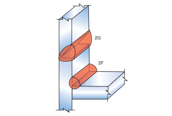
2F/2G Welding Positions
3. Vertical Position:
Uphill vs. Downhill Welding in Vertical Positions
Vertical welding can be done in two ways: “uphill” (↑), where the weld progresses from bottom to top, or “downhill” (↓), where it moves from top to bottom along the joint. The choice between these two techniques depends on factors such as material thickness, weld strength requirements, and welding speed.
Comparing Uphill and Downhill Welding
Uphill welding is more commonly used, especially for thicker materials and structural applications. When working on a large weldment that cannot be repositioned into the flat or horizontal position, uphill welding is often required to ensure deep penetration and strong weld integrity. The slower travel speed allows the molten puddle to fully fuse into the joint, creating a stronger weld.
In contrast, downhill welding is primarily used for speed, making it common in applications like pipeline welding and thin steel fabrication. However, its faster travel speed reduces penetration, as the arc tends to sit on top of the filler metal rather than penetrating into the root of the joint. This means that while a downhill weld may look good externally, it often lacks the depth and strength of an uphill weld, making it unsuitable for thicker materials and structural code welds.
A simple test confirms this difference—welding on the same material with identical settings and then cutting the welds in half reveals that uphill welds consistently show deeper penetration. Uphill welding requires careful puddle control to prevent dripping while allowing the weld to fuse properly, ensuring a structurally sound joint that can handle greater loads.
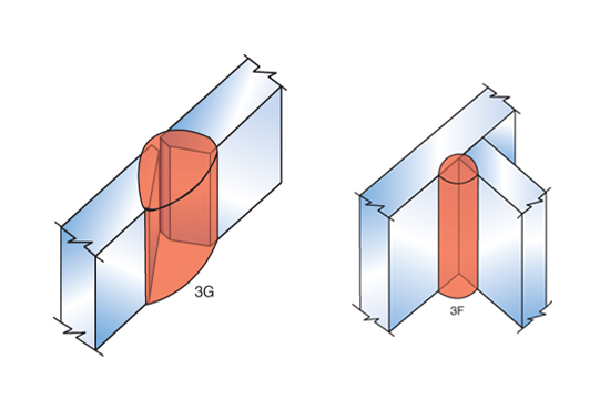
3G/3F Welding Positions
4. Overhead Position:
Overhead welding is essentially 1G flipped 180°, but the challenge lies in the uncomfortable position. Unlike flat welding, you have to fight against gravity, making precise control and technique crucial.
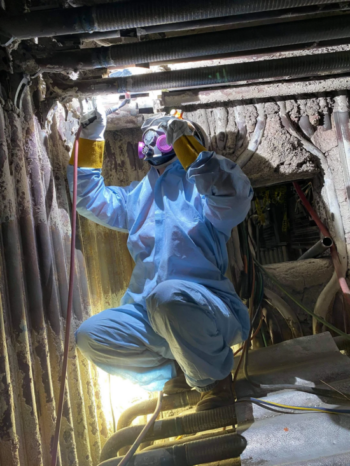
A steady hand and good positioning are key. Tossing the welding lead over your shoulder helps push the stinger upward with better control. Keep the arc length minimal and stay tight to the workpiece to prevent excessive spatter and weak fusion.
Speed matters—move too slow, and you’ll have large globs of molten metal falling on you. Even at the right speed, sparks and slag will still drop, so wearing proper PPE, including leathers, is essential. Never stand directly under the sparks to avoid burns or injuries.
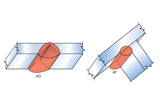
4G/4F Overhead Positions
FAQ:
Are Downhill and Down Hand the Same?
No, they are different terms with different meanings. Downhill welding refers to welding vertically from top to bottom. Down hand is an old-school term for flat or horizontal welding, meaning the weld is positioned below your hand as you work.
How to Prevent Molten Metal Drops in Overhead Welding and Their Effects?
Spatter is Inevitable – Control it by keeping voltage steady and increasing wire feed speed until you feel slight pushback, then back off 5-10 WFS. This helps maintain a good weld profile and a stable puddle, reducing the chances of drips.
Avoid pointing the electrode or torch directly upward, as molten metal can drip into the nozzle and tip, causing clogs and affecting gas flow. While nozzles and tips are inexpensive and easy to replace, if spatter enters the gooseneck, it can cause costly damage. Some torches, like the ESAB PSF 405 MIG welding torch(By CNAWELD), include a spatter protection device in the nozzle, preventing molten metal from entering the neck and ensuring longer durability of the torch.
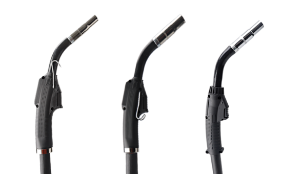
ESAB PSF 405 MIG Welding Torch-CNAWELD
Conclusion:
Now we have learned the four basic welding positions: Flat (1G/1F), Horizontal (2G/2F), Vertical (3G/3F), and Overhead (4G/4F). Each position presents unique challenges, requiring adjustments in technique, travel speed, and arc control. Flat welding is the easiest due to minimal gravity influence, while horizontal and vertical welding demand better puddle control. Overhead welding is the most difficult, requiring precise positioning and PPE for safety.
Mastering these positions is essential for producing strong, reliable welds in different applications. With practice and proper technique, welders can confidently adapt to any welding scenario.